Navigation

    • Register
    • Login
    • Search
    • Categories
    • Recent
    • Tags
    • Popular
    1. Home
    2. Jose
    Jose

    Jose

    @Jose

    0
    Reputation
    3
    Posts
    346
    Profile views
    0
    Followers
    0
    Following
    Joined Last Online

    • Profile
    • More
      • Following
      • Followers
      • Topics
      • Posts
      • Best
      • Groups
    Jose Follow

    Posts made by Jose

    OpenIMU300ZI connection questions.

    Hello

    I have some doubts about the connection of the OpenIMU300ZI.

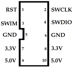
    I have a st-link / v2 with the following pins:
    alt text

    On the other hand I have an FT232RL like the following:
    alt text

    Finally I have an gps module like the following:
    alt text

    I know you recommend the evaluation kit, but I have these components and I want to take advantage of them to make tests.
    Also, for the final install, I'd prefer something smaller than the evaluation kit.

    My doubt is the connections I have to make, direct from the OpenIMU300ZI to the components that I have listed before.
    I wanted to know if the ones I list below are correct and sufficient.

    OpenIMU300ZI - st-link / v2
    8 NRST - 1 RST
    18 SWCLK - 2 SWCLK
    16 SWDIO - 4 SWDIO
    13 GND - 5 GND
    10 VIN 5V - 9 5V

    OpenIMU300ZI - FTD232RL
    11 VIN 5V - VCC
    14 GND - GND
    3 TX0 - RX0
    4 RX0 - TX0

    OpenIMU300ZI - GPS
    12 VIN 5V - VCC
    15 GND - GND
    5 TX1 - RX
    6 RX1 - TX

    I would have to jumper pin 7 SPI / UART with any GND

    Finally, the following pins would be free
    OpenIMU300ZI: 1, 2, 9, 17, 19, 20
    ST-LINK/V2: 3-DWIN, 6-GND, 7-3.3V, 8-3.3V, 10-5V
    FTD232RL: RTS, CTS

    I also wanted to know if in this case it is necessary to power from an external source or if the FTD232RL that provides 5V from the computer's USB is sufficient

    With all these connections, could I program without problem using the stlink / v2 or the FT232RL and through the ST software or through Visual Studio Code and also connect to https://developers.aceinna.com/devices/record-next?

    Many thanks!

    Best regards!

    posted in The OpenIMU Family •
    RE: IMU placement into a car

    @Dong-xiaoguang said in IMU placement into a car:

    hard iron. For example, a moving magnet, a chaning current around the sensor;
    soft iron. For example, a moving steel.
    Environmental magnetic field change. For example, moving the sensor for one location to another which has a different magnetic north from the first location.

    Thank you for your commnets, I've tried it without succes, but I'm more interested in the Aceinna hardware because I'm in doubt about buy it. My main questions are:

    @Jose said in IMU placement into a car:

    Can you assure us that this that we have tried to describe does not happen with your module?
    What is the optimal location for the module?What are the possible ones?Where have they tried it?
    On the other hand, is there a possibility to connect with Arduino?

    Best regards, Jose

    posted in The OpenIMU Family •
    IMU placement into a car

    Hello

    We are thinking about acquiring one of your units, specifically the OpenIMU300ZI

    The idea is to use it as magnetic heading and attitude indicator on ultralight, fiberglass, all-metal, wood, or mixed aircraft.

    We are currently testing with other sensors on the market, such as the bno080, mpu9250, RM3100, among others, and we are having problems due to interference with the magnetometer. It is impossible get a steady, but out the car is steady and accurate.

    At the moment we are testing in a car.

    We have tested with the engine on and off, in the center of the car and in the back seat, all this calibrating the magnetometers and other sensors in the car with the corresponding settings.

    We want to buy your system for two reasons, the first one being stability against acceleration, braking and cornering. In the systems we are testing, the kalman filters that we use the filter interpret that I go with the nose up, when this is not the case, the same thing happens in other situations.

    On the other hand, we are interested in the interferences of the magnetometer by the electronics and the motor.

    Can you assure us that this that we have tried to describe does not happen with your module?
    What is the optimal location for the module?What are the possible ones?Where have they tried it?
    On the other hand, is there a possibility to connect with Arduino?

    Thank you and congratulations on the project. Sorry for the english...

    posted in The OpenIMU Family •