OpenIMU algorithm response after shock

Hi all,

I tested the OpenIMU algorithm using a 6D (Acc+Gyro) MEMS on a custom board. I used the example for OpenIMU300RI VG_AHRS (can bus) and the selected algorithm is VG.

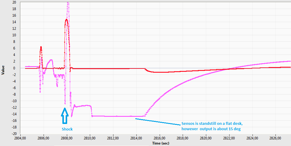
Under linear vibrations the outputs change a little; it is OK. But after a shock(if you hit the sensor to the desk), it takes too much time(15-20s) for the sensor to output correct values. Please see the image below. I think it is a big problem if the device operates on a vehicle. I think acceleration gain too low even if the sensor is standstill on a desk. Is there a dynamic gain adjustment in the algorithm?

imu_problem.png

I have also another question. How can I modify the library to use update rate others than 100/200Hz? My MEMS supports 104/208Hz. Please see the code below.

// Set dt based on the calling frequency of the EKF
if (gAlgorithm.callingFreq == FREQ_100_HZ)
{
    gAlgorithm.dt = (real)(0.01);
    gAlgorithm.dITOW = 10;
}
else if (gAlgorithm.callingFreq == FREQ_200_HZ)
{
    gAlgorithm.dt = (real)(0.005);
    gAlgorithm.dITOW = 5;
}
else
{
    while (1);
}

This is caused by a compromise between linear accel rejection and convergence speed. From our practical applications, this causes no problem becuase shock rarely happens on a real vehicle. From your fig, there could even be gyro saturation. Besides, the algorithm is only tuned for our OpenIMU. To use it on your own IMU, you need to know the characteristics of your IMU and change the algorithm accordingly.

If this really bothers you, you can refer to the code for the dynamic measurement cov adjustment and change the corresponding code. The code is in void _GenerateObservationCovariance_AHRS(void) in UpdateFunctions.c.

To modify the update rate, the code you mentioned should be changed. However, I believe there might be other parts should be changed, too.

I have also performed a test with MTLT305D. The response was similar. It may cause big problems in some cases.

Acceleration measuring range was 4g and the gyro range was 500dps in my test setup. It supports up to 16g/2000dps respectively. Should I increase the range?

To change update rate, filter coefficients may also be changed. In EKF_UpdateStage() function, timer.oneHundredHertzFlag is used. Is it necessary to perform the update at 100Hz? I don't have a GPS module.
if( gAlgorithm.state <= LOW_GAIN_AHRS )
{
// Only allow the algorithm to be called on 100 Hz marks
if(timer.oneHundredHertzFlag == 1)
{
// Update the AHRS solution at a 10 Hz update rate
// Subframe counter counts to 10 before it is reset
if( _CheckForUpdateTrigger(TEN_HERTZ_UPDATE) )
{
/* The AHRS/VG solution is handled inside FieldVectorsToEulerAngles
* (called from the prediction function EKF_PredictionStage)
*/
ComputeSystemInnovation_Att();
Update_Att();
}
}
}

I think the value below must be re-calculated for my MEMS. Can you provide the Matlab script used for the calculation?

     * These values are found by passing the accelerometer VRW values
     * (determined from a very limited data set) through a Matlab
     * script which generates the roll and pitch noise based on the
     * sensor noise.  The value below is the 1-sigma value at 0
     * degrees.  The quadratic correction below is meant to increase
     * R as the angle increases (due to the geometry and
     * mathematical function used to compute the angle).
     *
     * Matlab script: R_Versus_Theta.m
     */
    switch (sysRange)
    {
        case _200_DPS_RANGE:
            // -200 VRW value (average x/y/z): 7.2e-4 [(m/sec)/rt-sec]
            Rnom = (real)9.82e-07;  // (9.91e-4)^2
            break;
        case _400_DPS_RANGE:
                // -400 VRW value (average x/y/z): 8.8e-4 [(m/sec)/rt-sec]
            Rnom = (real)1.54e-06;  // (1.24e-3)^2
            break;
    }

I don't have the Matlab script, either.

Log in to reply