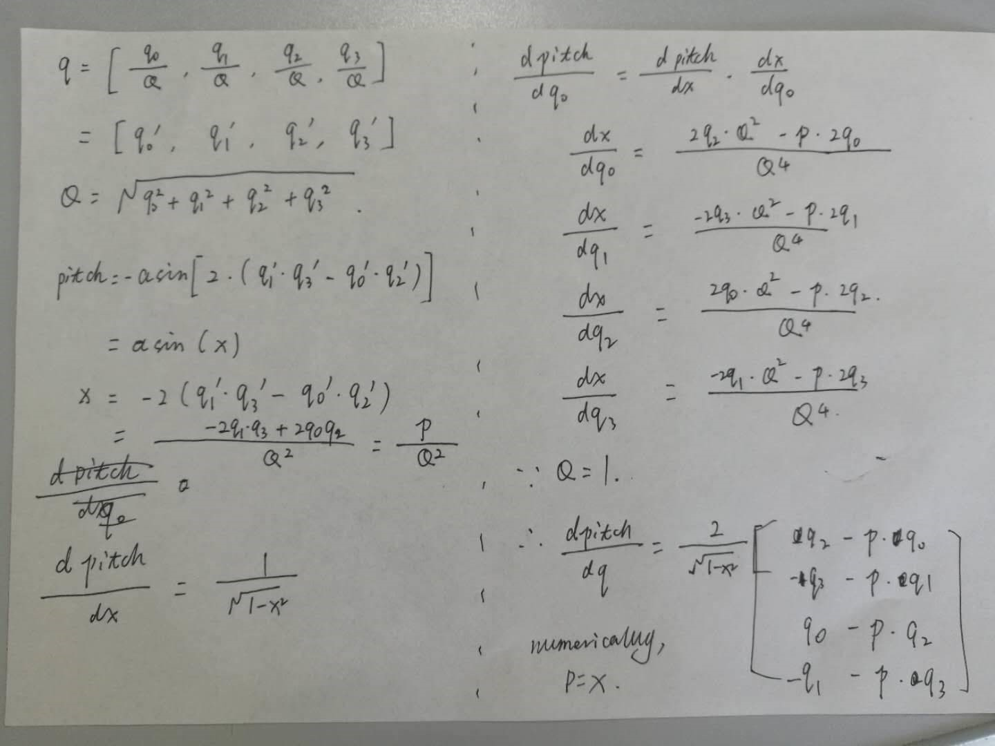
I found the derivation. I have used numerical differential of quaternion as reference to compare the two formula. The one with constraint did give better accuracy when pitch and roll are not close to 0.

Posts made by Dong xiaoguang
Hello,
I think you are right. Just a reminder that the measured velocity in the body frame is no longer [frontVelMean, 0, 0] now. You may also rename Update_PseudoMeasurement() to something else because you are using actual measurements instead of pseudo ones.
Position and velocity are not required by the AHRS app. By saying AHRS app, we usually mean only attitude is calculated and the heading angle is stabilized by the magnetic heading.
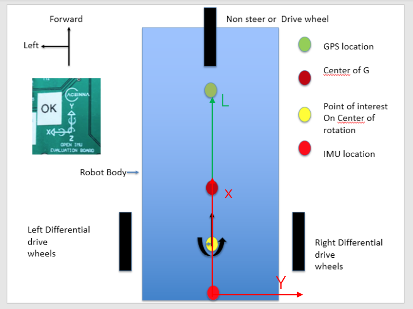
First, please make the X axis of the IMU point to the direction of travel. Otherwise, heading accuracy may be degraded.
After doing that, you get the following diagram. L is the lever arm vector and has a positive component along the X axis of the IMU.

- point of interest is a point whose position you want to measure. The algorithm will use this config to convert the position of IMU to the position of this point.
- As mag is not used, its configurations don't matter. When soft iron ratio is set 1 and soft iron angle to 0, it means there is no soft iron interference.
Hi,
First, the lever arm is defined as the position of the GPS antenna relative to the IMU.
Second, the relative position vector is represented in the IMU body frame. And leverArmBx, leverArmBy and leverArmBz are three components of this vector in the IMU body frame.
Could you share with us some data file or plots where this issue occurs? Thank you.
I haven't seen anybody has done some thing like this with OpenIMU.
Oh, I just had the similar problem a few days ago. I found the soft reset command "55555352007E4F" in hex.
@Jose said in IMU placement into a car:
Can you assure us that this that we have tried to describe does not happen with your module?
If you mean magnetic interferences, we will have the same problem.
If you mean pitch/roll error increase duration acceleration or braking, we have this into consideration in our algorithm. However, there will still be error increase. You need to test it to see if it meets your requirements.
What is the optimal location for the module?What are the possible ones?Where have they tried it?
For magnetic sensor, you need to put it aways from changing interferences.
You should also put it at a location with less vibration.
On the other hand, is there a possibility to connect with Arduino?
We have SPI and UART in OpenIMU300ZI. You need to prepare the driver for Arduino.
There is one simple principle when you want to use a magnetometer in your application: there should be no varying magnetic interference.
Varying magnetic interference includes:
- hard iron. For example, a moving magnet, a chaning current around the sensor;
- soft iron. For example, a moving steel.
- Environmental magnetic field change. For example, moving the sensor for one location to another which has a different magnetic north from the first location.
@Swingw , you buy an OpenIMU300ZI evk.
@simon-rob , I will find the firmware engineer to answer your question.
Hi Simonrob,
Could you tell me more details about what you want to do? So, I can get a firmware engineer to help you.
Dong
Hi matteo,
I tried both the jumper ON and OFF, it worked fine.
When I first got this app to work, I tried the following steps. You can follow these steps.
- Are you using the latest code? The latest code should be released around late in 2019. If no, get the latest code and then continue. If yes, Continue.
- In the function TaskGps() in taskGps.c, you can check (by debugging in vscode or outputting debug messages) if the app can run to the line
GPSHandler();
If not(unlikely), please tell me. If yes, that means the taskGps is working, and continue.
3. In GPSHandler(), check if the app can run into
_handleGpsMessages(gGpsDataPtr);
and then into
parseNMEAMessage(tmp, gpsMsg, GPSData);
If so, that means the app can run into the GNSS message decoder as in UserConfiguration.C, and continue. If not, you need to check your configuration.
4. In parseNMEAMessage(), you can see the final results. There are a few things you can do.
4.1 check if gpsMsg contains actual NMEA messages.
4.2 check if the app can run into processNMEAMessage().
4.3 in processNMEAMessage(), check if the app can run into _handleNMEAmsg().
4.4 and in _handleNMEAmsg(), you can check if all three messages can be decoded.
You can actually directly check step4.
In a serial monitor, can you see other messages than NMEA GGA/VTG/RMC? There may be some binary-format packets that should be disabled. Besides, are you sure the GPS protocol in the INS app is configured to NMEA?
If the above are confirmed, you need to dive into the taskGps.c to figure out why.
Hi Amin,
gAlgorithm.Behavior.bit.useGPS is used to control state transition. If it is set to false, the algorithm will stay in attitude only mode. This bit does not control the use of each GPS sample. To do that, you need to use gEKFInput.gpsFixType. Setting this bit to false means this GPS measurement is invalid and will not be used in the EKF update stage. You can either directly change this bit or change the GPS driver where this bit get its value.
Dong
Since you make it work sometimes, I assume the connection and baud rate are right. So you can first check if NMEA is the only output message via ucenter. You can do this using some serail tool on PC to see the output from the receiver.
You can. However, you may need change a lot of things. First, you need to create your own interface from OpenIMU300ZA to your sensor. Second, you need to change the algorithm to update the error model of your sensor. Third, you need to take care of the data sampling rate.
GPS visibility should be an input to the INS app. All the application source code is open-source, and you can do anything to it. To add a command, our firmware engineer deisgn a good framework to do that. To add GPS signal status in e2 packet, it is also very easy because all UART messages are customizable. You just need to spend more time on the source code.
Dong