IMU Offset to the GPS

Hi
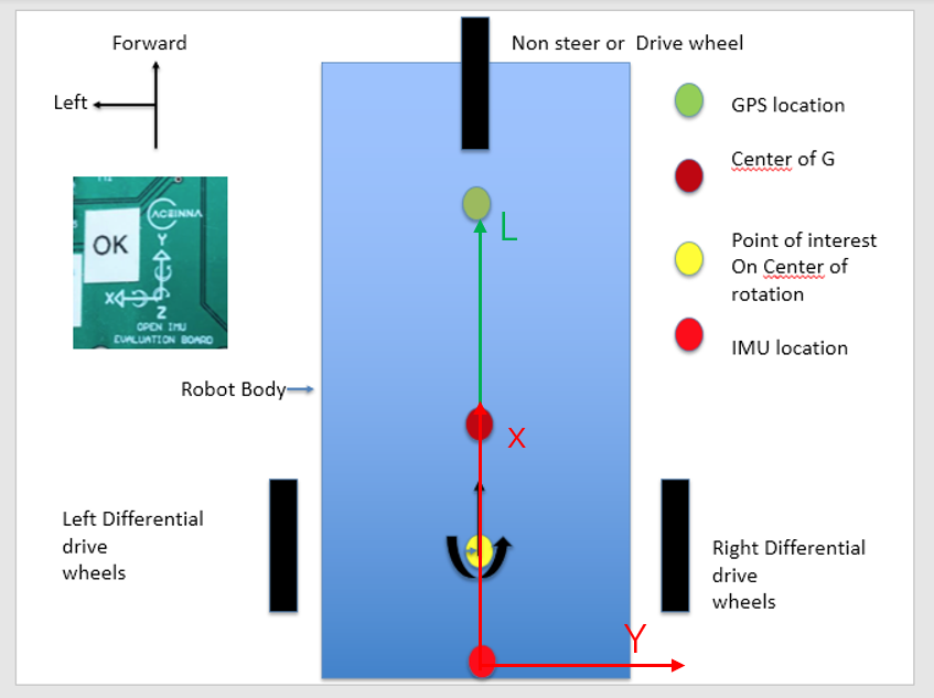
In userconfiguration you have these variables. I want to locate the variables used to define the offsets between the GPS antenna and the IMU. Are these the variables and what is their sense do you have a diadram ie what is the difference between - and + x and - and + y. Same for Z

with regard to orientation what would - signs do to the orientation ie do you have a diagram
.leverArmBx = 0.0,
.leverArmBy = 0.0,
.leverArmBz = 0.0,

Hi,
First, the lever arm is defined as the position of the GPS antenna relative to the IMU.
Second, the relative position vector is represented in the IMU body frame. And leverArmBx, leverArmBy and leverArmBz are three components of this vector in the IMU body frame.

@Dong-xiaoguang
Can you please be more specific. Can you use the enclose diagram to show if the number should be positive or negative.
For example if the IMU is located at the bottom of the diagram and the pointofinterest is at the center of rotation and the gps is in front of both points would the value be positive or negative. Same for the other axes
I am assuming that the IMU is positioned so that Y axis of the printed arrow is pointing in the direction of travel of the robot and imu and that a turn to x would be a turn to the left

5f991399-5e1a-41c2-8ee9-de48b6e98f02-image.png
cid:image001.png@01D6E823.708C4A70

First, please make the X axis of the IMU point to the direction of travel. Otherwise, heading accuracy may be degraded.
After doing that, you get the following diagram. L is the lever arm vector and has a positive component along the X axis of the IMU.
图片1.png

many thanks. This product seems very good

Log in to reply